New Turbostart Hydromechanical Jolly Couplings
Requiring minimal maintenance and long service life makes them suitable for demanding industrial applications.
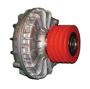
The worldwide patented Jolly hydromechanic coupling is a fitting of outstanding importance, which is widely used in modern transmissions. The Jolly coupling makes it possible to start high inertia loads gradually using three phase squirrel cage asynchronous motors, which demand constant continuous running however the load changes.
The Jolly Coupling is unique in combining the advantages of both fluid and mechanical device to provide fuIl protection, yet save substantially on capital, maintenance and costs.
Benefits
- Soft starts (fig. C)
- Dampens shock loads.
- Energy savings by reducing initial starting current using a smaller motor according to the demand power at the rated speed (fig. D)
- Varying the quantity of fluid makes it easy to match motor to drive requirements and provides optimum acceleration times.
- Optional reservoir permits extended startup time.
- No slip at full speed and no heat generation.
- Optional temperature-limiting fusible plug provides protection in case of prolonged overloads.
- Output speed kept at a constant level and in any case the same as the motor.
- No wear and fatigue on mechanical lockup device.
- No maintenance required but periodic oil change.
Applications
- Air separators
- Carding machines
- Paper machineries
- Amusement Park rides
- Centrifugal pumps
- Polverisers
- Belts conveyors
- Compressors
- Rotating filters
- Blowers
- Fans
- Textile machines
- Bottling machines
- Machine tools
- Wire machines
- Bucket conveyors
- Metalworking machines
- Wheel balancing machines
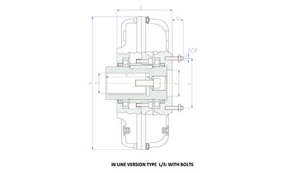
In Line Version Type L/S
| Dimenisons | ||||||||
|---|---|---|---|---|---|---|---|---|
| Coupling type | A | C ±0,5 | D G7* | e min | E H7 | F ±0,2 | G ±1 | Stud bolts |
| 12 | 234 | 127 | 24 – 28 38 | 60 80 | 47 | 73 | 16 | 6 M6 |
| 13 | 260 | 146 | 28 38 42 | 60 80 110 | 47 | 73 | 16 | 6 M6 |
| 14 | 294 | 148 | 38 42 – 48 | 80 110 | 62 | 89 | 25 | 6 M8 |
| 15 | 325 | 154 | 42 48 – 55 | 110 | 62 | 89 | 25 | 6 M8 |
| 16 | 365 | 183 | 48 – 55 60 – 65 | 110 140 | 72 | 112 | 30 | 8 M10 |
| 16N | 390 | 181 | 48 – 55 60 – 65 | 110 140 | 85 | 136 | 30 | 8 M10 |
| 17 | 430 | 216 | 55 60 – 65 – 75 80 | 110 140 170 | 85 | 136 | 30 | 8 M10 |
| 18 | 527 | 239 | 65 – 75 80 100 | 140 170 210 | 120 | 168 | 35 | 8 M10 |
| 19 | 626 | 259 | 80 100-110 | 170 210 | 140 | 196 | 45 | 10 M12 |
| 110 | 800 | 325 | 100 – 110 – 120 130 | 210 240 | 180 | 250 | 50 | 10 M14 |
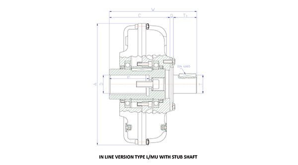
In Line Version Type L/MU
| Dimensions | ||||||||
|---|---|---|---|---|---|---|---|---|
| Coupling type | A | C ±0,5 | D G7* | e min | Q | T h6 | T1 | W |
| 12 | 234 | 127 | 24 – 28 38 | 60 80 | 8 | 24 | 31 | 165 |
| 13 | 260 | 146 | 28 38 42 | 60 80 110 | 8 | 30 | 39 | 192 |
| 14 | 294 | 148 | 38 42 – 48 | 80 110 | 8 | 38 | 46 | 202 |
| 15 | 325 | 154 | 42 48 – 55 | 110 | 10 | 48 | 66 | 230 |
| 16 | 365 | 183 | 48 – 55 60 – 65 | 110 140 | 10 | 52 | 66 | 259 |
| 16N | 390 | 181 | 48 – 55 60 – 65 | 110 140 | 10 | 55 | 70 | 261 |
| 17 | 430 | 216 | 55 60 – 65 – 75 80 | 110 140 170 | 10 | 55 | 70 | 296 |
| 18 | 527 | 239 | 65 – 75 80 100 | 140 170 210 | 12 | 70 | 85 | 336 |
| 19 | 626 | 259 | 80 100-110 | 170 210 | 25 | 80 | 100 | 484 |
| 110 | 800 | 325 | 100 – 110 – 120 130 | 210 240 | 28 | 110 | 160 | 513 |
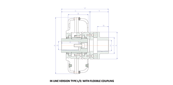
In Line Version Type L/E
| Dimensions | ||||||||||||
|---|---|---|---|---|---|---|---|---|---|---|---|---|
| Coupling type | Flexible Coupling | A | B | C ±0,5 | D G7* | e min | H G7 max | I | N | X | Y | V |
| 12 | E 20 | 234 | 98 | 127 | 24 – 28 38 | 60 80 | 38 | 55 | 42 | 96 | 76 | 202 |
| 13 | E 20 | 260 | 105 | 146 | 28 38 42 | 60 80 110 | 38 | 55 | 42 | 96 | 76 | 221 |
| 14 | E 30 | 294 | 107 | 148 | 38 42 – 48 | 80 110 | 48 | 76 | 55 | 122 | 95 | 243 |
| 15 | E 30 | 325 | 125 | 154 | 42 48 – 55 | 110 | 48 | 76 | 55 | 122 | 95 | 249 |
| 16 | E 40 | 365 | 130 | 183 | 48 – 55 60 – 65 | 110 140 | 60 | 86 | 72 | 150 | 119 | 302 |
| 16N | E 50 | 390 | 145 | 181 | 48 – 55 60 – 65 | 110 140 | 70 | 105 | 72 | 175 | 119 | 300 |
| 17 | E 50 | 430 | 160 | 216 | 55 60 – 65 – 75 80 | 110 140 170 | 70 | 105 | 72 | 175 | 119 | 335 |
| 18 | E 60 | 527 | 195 | 239 | 65 – 75 80 100 | 140 170 210 | 80 | 124 | 88 | 220 | 142 | 381 |
| 19 | E 70 | 626 | 225 | 259 | 80 100-110 | 170 210 | 100 | 150 | 111 | 250 | 181 | 440 |
| 110 | E 80 | 800 | 320 | 325 | 100 – 110 – 120 130 | 210 240 | 110 | 200 | 141 | 320 | 226 | 551 |
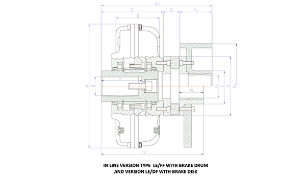
In Line Version Type L/E – FF/DF
| Dimensions | ||||||||||||||
|---|---|---|---|---|---|---|---|---|---|---|---|---|---|---|
| Coupling type | A | B | C ±0,5 | D G7* | e min | G ± 1 | H G7 max | I | N | X | X1 | Y | Y1 | V1 |
| 12 | 234 | 98 | 127 | 24 – 28 38 | 60 80 | 16 | 38 | 55 | 42 | 96 | 160 | 76 | 60 | 202 |
| 13 | 260 | 105 | 146 | 28 38 42 | 60 80 110 | 16 | 38 | 55 | 42 | 96 | 160 | 76 | 60 | 221 |
| 14 | 294 | 107 | 148 | 38 42 – 48 | 80 110 | 25 | 48 | 76 | 55 | 122 | 160 | 95 | 60 | 243 |
| 15 | 325 | 125 | 154 | 42 48 – 55 | 110 | 25 | 48 | 76 | 55 | 122 | 160 200 | 95 | 60 75 | 249 |
| 16 | 365 | 130 | 183 | 48 – 55 60 – 65 | 110 140 | 30 | 60 | 86 | 72 | 150 | 160 200 | 119 | 60 75 | 302 |
| 16N | 390 | 145 | 181 | 48 – 55 60 – 65 | 110 140 | 30 | 70 | 105 | 72 | 175 | 250 315 | 119 | 95 118 | 300 |
| 17 | 430 | 160 | 216 | 55 60 – 65 – 75 80 | 110 140 170 | 30 | 70 | 105 | 72 | 175 | 250 315 | 119 | 95 118 | 335 |
| 18 | 527 | 195 | 239 | 65 – 75 80 100 | 140 170 210 | 35 | 80 | 124 | 88 | 220 | 315 400 | 142 | 118 150 | 381 |
| 19 | 626 | 225 | 259 | 80 100-110 | 170 210 | 45 | 100 | 150 | 111 | 250 | 400 500 | 181 | 150 190 | 440 |
| 110 | 800 | 320 | 325 | 100 – 110 – 120 130 | 210 240 | 50 | 110 | 200 | 141 | 320 | 500 | 226 | 190 | 551 |
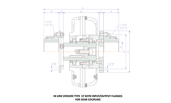
In Line Version Type CF
| Dimensions | ||||||||||
|---|---|---|---|---|---|---|---|---|---|---|
| Coupling type | A | W1 | B | D | G | M ±0,1 | N | n° Ø | n1° Ø | P Ø MAX |
| 12 | 369 | 126 | 51,5 | 19 | 19 | 122 | 152 | 8 10 | 8 M10 | 60 |
| 13 | 388 | 145 | 51,5 | 19 | 19 | 122 | 152 | 8 10 | 8 M10 | 60 |
| 14 | 419 | 152 | 63,5 | 19 | 19 | 148 | 180 | 10 10 | 10 M10 | 75 |
| 15 | 478 | 156 | 78,5 | 22 | 22 | 178 | 215 | 10 12 | 10 M12 | 75 |
| 16 | 523 | 183 | 78,5 | 22 | 22 | 178 | 215 | 10 12 | 10 M12 | 110 |
| 16N | 533 | 181 | 78,5 | 22 | 22 | 178 | 215 | 10 12 | 10 M12 | 110 |
| 17 | 596 | 216 | 92,5 | 22 | 22 | 203 | 240 | 12 12 | 12 M12 | 110 |
| 18 | 753 | 265 | 108 | 28,5 | 28,5 | 236 | 280 | 12 16 | 12 M16 | 127 |
| 19 | 855 | 285 | 123 | 28,5 | 28,5 | 270 | 320 | 14 16 | 14 M16 | 150 |
| 110 | 948 | 352 | 123 | 28,5 | 28,5 | 270 | 320 | 14 16 | 14 M16 | 150 |
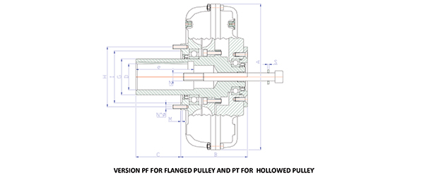
Pulley Versions Type P
| Dimensions | ||||||||||||
|---|---|---|---|---|---|---|---|---|---|---|---|---|
| Coupling type | A | B | C | D | e min | G | H | I | M | N | N° Ø | |
| 14 PF | 294 | 143 | 110 | 38 42 48 | 80 110 | 65 | 114 | 90 | 5,5 | M 12 M 16 | 8 M8 | |
| 15 PF | 325 | 163 | 110 | 42 48 55 | 110 | 75 | 114 | 90 | 5,5 | M 16 M 20 | 8 M8 | |
| 16 PF | 365 | 171 | 110 126 | 48 55 60 65 | 110 140 | 90 | 150 | 130 | 4 | M 20 | 8 M10 | |
| 16N PF | 390 | 195 | 126 | 48 55 60 65 | 110 140 | 90 | 150 | 130 | 4 | M 20 | 8 M10 | |
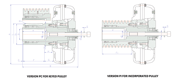
Specifications – Pulley Versions Type PC/PI
| Dimensions | ||||||||||||||||
|---|---|---|---|---|---|---|---|---|---|---|---|---|---|---|---|---|
| Coupling type | A | B ± 1,5 | C ± 1 | D1 h6 | D (G7) | e min | F | G ± 1,5 | H | L | M | N Ø max screws | O Puller | F1 | R | S |
| 12 | 234 | 215 | 2,5 | 85 | 24 28 38 | 60 80 | 80 | 22 | 14 | 88,5 | 12 X 8 | M12 | M14 | 95 | 88 | 2,5 |
| 13 | 260 | 240 | 7 | 85 | 28 38 | 60 80 | 80 | 31 | 22 | 88,5 | 12 x 8 | M12 | M14 | 110 | 88 | 2,5 |
| 14 | 294 | 244 | 2,5 | 95 | 38 42 48 | 80 110 | 80 | 29 | 20 | 98,5 | 12 X 8 | M16 | M20 | 110 | 104 | 2,5 |
| 15 | 325 | 286 | 5 | 110 | 42 48 55 | 110 | 110 | 30 | 18 | 115 | 16 x 10 | M16 | M20 | 135 | 115 | 2,5 |
| 16 | 365 | 340 | 4 | 125 | 48 55 60 65 | 110 140 | 130 | 51 | 46 | 130 | 18 x 11 | M20 | M24 | 180 | 135 | 4 |
| 16N | 390 | 340 | 3 | 125 | 48 55 60 65 | 110 140 | 130 | 42 | 34 | 130 | 18 x 11 | M20 | M24 | 180 | 135 | 4 |
| 17 | 430 | 451 | 3,5 | 150 | 55 60 65 75 80 | 110 140 170 | 150 | 109 | 100 | 156 | 20 x 12 | M20 | M24 | 255 | 160 | 4 |
| 18 | 527 | 488 | 4 | 150 150 160 170 | 75 80 90 95** 100** | 140 170 170 230 | 150 150 230 230 | 121 40 | 101 20 | 156 156 166 176 | 20 x 12 | M24 | M30 | 255 | 160 175 | 4 |
| 19 | 626 | 560 | 5 | 190 | 80 90 100 110 | 170 210 | 280 | 43 | 25 | 195,5 | 25 x 14 | M24 | M30 | 310 | 215 | 6 |
Version D110
| Coupling | Dimensions | |||||||||||||
|---|---|---|---|---|---|---|---|---|---|---|---|---|---|---|
| A ±2 | C ±3 | D m6 | E | F | G | H | I | L | M | N | O | P | KG | |
| D 110 | 852 | 1310 | 140 | 140 | 793,5 | 258,5 | 36 | 135 | 413,5 | 1030 | 488 | 409 | 160 | 880 |
Resources